(Hong Kong)

Product Summary
nverters, Converters, DC choppers, Induction heating, DC to DC converters
ation nge. pecific to cha final s subject re is nic limits Th tr Notice parame Som
APPLICATION Inverters, Converters, DC choppers, Induction heating, to DC converters.
HVIGBT MODULES (High Voltage Insulated Gate Bipolar Transistor Modules) Feb.1999
. ation nge. pecific to cha final s subject re is nic limits Th tr Notice parame Som
2nd-Version HVIGBT (High Voltage Insulated Gate Bipolar Transistor) Modules
Parametrics
Symbol VCES VGES IC ICM I E (Note 1) I EM(Note P C (Note Tj T stg Viso Parameter Collector-emitter voltage Gate-emitter voltage Collector current Emitter current Maximum collector dissipation Junction temperature Storage temperature Isolation voltage Mounting torque Weight Conditions G-E Short C-E Short = 25°C Pulse = 25°C Pulse = 25°C Main terminal to Bass, AC for 1 minute Main terminals screw M8 Mounting screw M6 Auxiliary terminals screw M4 Typical value Ratings Unit °C V N·m kg
Symbol ICES Parameter Test conditions VCE = VCES, VGE = 120mA, VCE = 10V VGE = VGES, VCE 125 °C VCE = 10V VGE = 0V VCC = 1200A, VGE = 15V VCC = 1.6 Resistive load switching operation = 1200A, VGE = 1200A, die / μs IGBT part FWDi part Case to fin, conductive grease applied Min 4.5 Limits Typ Max Unit μs μC °C/W
Collector cutoff current Gate-emitter VGE(th) threshold voltage IGES Gate-leakage current Collector-emitter VCE(sat) saturation voltage Cies Input capacitance Coes Output capacitance Cres Reverse transfer capacitance QG Total gate charge td (on) Turn-on delay time tr Turn-on rise time td (off) Turn-off delay time tf Turn-off fall time V EC(Note 1) Emitter-collector voltage t rr (Note 1) Reverse recovery time Q rr (Note 1) Reverse recovery charge Rth(j-c)Q Thermal resistance Rth(j-c)R Rth(c-f) Contact thermal resistance
IE, VEC, rr , Qrr & die/dt represent characteristics of the anti-parallel, emitter to collector free-wheel diode. Pulse width and repetition rate should be such that the device junction temp. (Tj) does not exceed T jmax rating. Junction temperature (Tj) should not increase beyond 150° C. Pulse width and repetition rate should be such as to cause negligible temperature rise.
Features
HIGH POWER SWITCHING USE INSULATED TYPE
Diagrams

| Image | Part No | Mfg | Description |  |
Pricing (USD) |
Quantity | ||||
|---|---|---|---|---|---|---|---|---|---|---|
 |
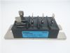
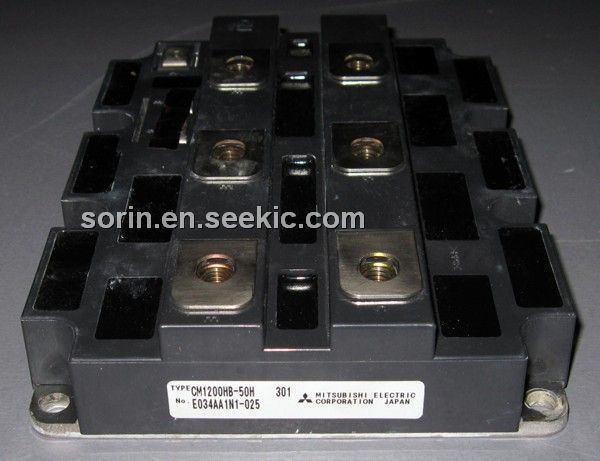
 CM1200HB-50H |
Other |
|
Data Sheet |
Negotiable |
|
||||
| Image | Part No | Mfg | Description | |
Pricing (USD) |
Quantity | ||||
|
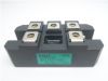
CM1200DB-34N |
Other |
|
Data Sheet |
Negotiable |
|
||||
|
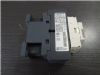
CM1200DC-34N |
Other |
|
Data Sheet |
Negotiable |
|
||||
|
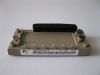
CM1200E4C-34N |
Other |
|
Data Sheet |
Negotiable |
|
||||
|
CM1200HA-24J |
|
IGBT MOD SGL 1200V 1200A H SER |
Data Sheet |
Negotiable |
|
||||
|
CM1200HA-34H |
Other |
|
Data Sheet |
Negotiable |
|
||||
|
CM1200HA-50H |
Other |
|
Data Sheet |
Negotiable |
|
||||