(Hong Kong)

Product Summary
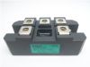
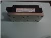
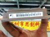
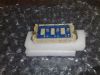
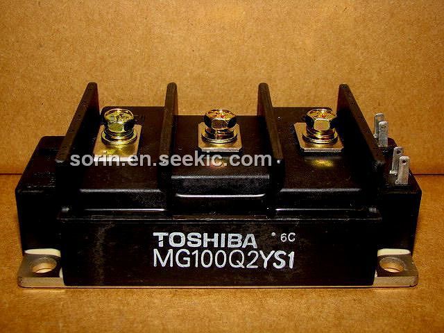
TOSHIBA IGBT Module Silicon N Channel IGBT
High Power & High Speed Switching Applications
High input impedance Enhancement-mode The electrodes are isolated from case.
Parametrics
Characteristics Gate leakage current Collector cut-off current Gate-emitter cut-off voltage Collector-emitter saturation voltage Input capacitance Turn-on delay time Rise time Switching time Turn-on time Turn-off delay time Fall time Turn-off time Forward voltage Reverse recovery time Thermal resistance Turn-on Switching loss Turn-off Eoff Symbol IGES ICES VGE (off) VCE (sat) Cies td (on) tr ton td (off) tf toff VF trr Rth (j-c) Eon 100 A, VGE 100 A, VGE -10 V, di/dt = 700 A/ms Transistor stage Diode stage Inductive load VCC 100 A VGE = 125°C Inductive load VCC 100 A VGE 9.1 W Test Condition VGE ±20 V, VCE = 0 VCE 1200 V, VGE = 100 mA, VCE 100 A, VGE = 125°C Min Typ. Max V ms °C/W ms Unit V pF
Features
TOSHIBA IGBT Module Silicon N Channel IGBT
Diagrams