(Hong Kong)

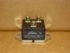
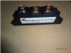
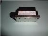
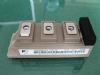
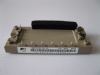
Product Summary
· High speed switching· Voltage drive· Low inductance module structure
Applications
Parametrics
Inverter for Motor drive· AC and DC Servo drive amplifier· Uninterruptible power supply· Industrial machines, such as Welding machinesAbsolute maximum ratings (at Tc=25°C unless otherwise specified)
Item Collector-Emitter voltage Gate-Emitter voltage Collector current Symbol VCES VGES IC ICp -IC pulse PC Tj Tstg Viso Conditions Rating to Unit V A
Collector Power Dissipation Junction temperature Storage temperature Isolation voltage between terminal and copper base *1 Screw Torque Mounting *2 Terminals *2
*1 : All terminals should be connected together when isolation test will be done. *2 : Recommendable value : Mounting to 3.5N·m(M5), Terminal 3.5 N·m(M5)
Item Zero gate voltage collector current Gate-Emitter leakage current Gate-Emitter threshold voltage Collector-Emitter saturation voltage Symbols ICES IGES VGE(th) VCE(sat) (terminal) VCE(sat) (chip) Cies ton tr tr(i) toff tf VF (terminal) VF (chip) rr R lead Conditions VGE=0V, f=1MHz VCC IC=400A VGE=±15V RG= Tj=25°C Tj=125°C Characteristics Min. Typ. Unit Max. nA V
Items Thermal resistance Contact Thermal resistance Symbols Rth(j-c) Rth(c-f)*4 Conditions IGBT FWD With thermal compound Characteristics Min. Typ. Unit Max. 0.16 °C/W
Features
IGBT Module U-series 600V / 400A
Diagrams