Product Summary
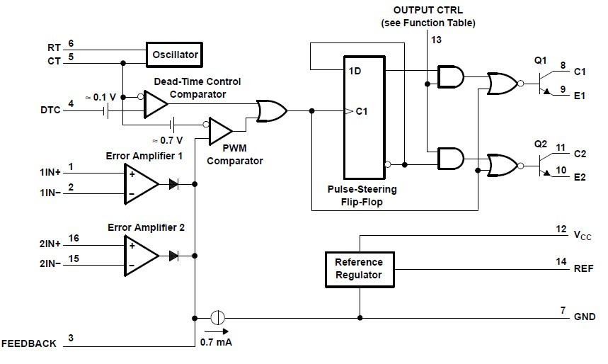
The TL494IDR is a pulse-width-modulation control circuit. The TL494IDR incorporates all the functions required in the construction of a pulse-width-modulation (PWM) control circuit on a single chip. Designed primarily for power-supply control, this device offers the flexibility to tailor the power-supply control circuitry to a specific application. The TL494IDR contains two error amplifiers, an on-chip adjustable oscillator, a dead-time control (DTC) comparator, a pulse-steering control flip-flop, a 5-V, 5%-precision regulator, and output-control circuits.
Parametrics
TL494IDR absolute maxing ratings: (1)VCC Supply voltage: max=41V; (2)VI Amplifier input voltage: max=VCC + 0.3 V; (3)VO Collector output voltage: max=41V; (4)IO Collector output current: max=250mA; (5)θJA Package thermal impedance: D package: max=73℃/W; DB package: max=82℃/W; N package: max=67℃/W; NS package: max=64℃/W; PW package: max=108℃/W; (6)Lead temperature 1,6 mm (1/16 inch) from case for 10 seconds: 260℃; (7)Tstg Storage temperature range: min=–65, max=150℃.
Features
TL494IDR features: (1)Complete PWM Power-Control Circuitry; (2)Uncommitted Outputs for 200-mA Sink or Source Current; (3)Output Control Selects Single-Ended or Push-Pull Operation; (4)Internal Circuitry Prohibits Double Pulse at Either Output; (5)Variable Dead Time Provides Control Over Total Range; (6)Internal Regulator Provides a Stable 5-V Reference Supply With 5% Tolerance; (7)Circuit Architecture Allows Easy Synchronization.
Diagrams

| Image | Part No | Mfg | Description |  |
Pricing (USD) |
Quantity | ||||||||||||
|---|---|---|---|---|---|---|---|---|---|---|---|---|---|---|---|---|---|---|
 |
 TL494IDR |
 Texas Instruments |
 Voltage Mode PWM Controllers Control Circuit |
 Data Sheet |

|
|
||||||||||||
 |
 TL494IDRE4 |
 Texas Instruments |
 Voltage Mode PWM Controllers Control Circuit |
 Data Sheet |

|
|
||||||||||||
 |
 TL494IDRG4 |
 Texas Instruments |
 Voltage Mode PWM Controllers PWM Control Circuit |
 Data Sheet |

|
|
||||||||||||
 (Hong Kong)


